Reviews
Flypro XJaguar - Build Log & Review
Posted on November 20, 2016 • 11 min read • 2,245 words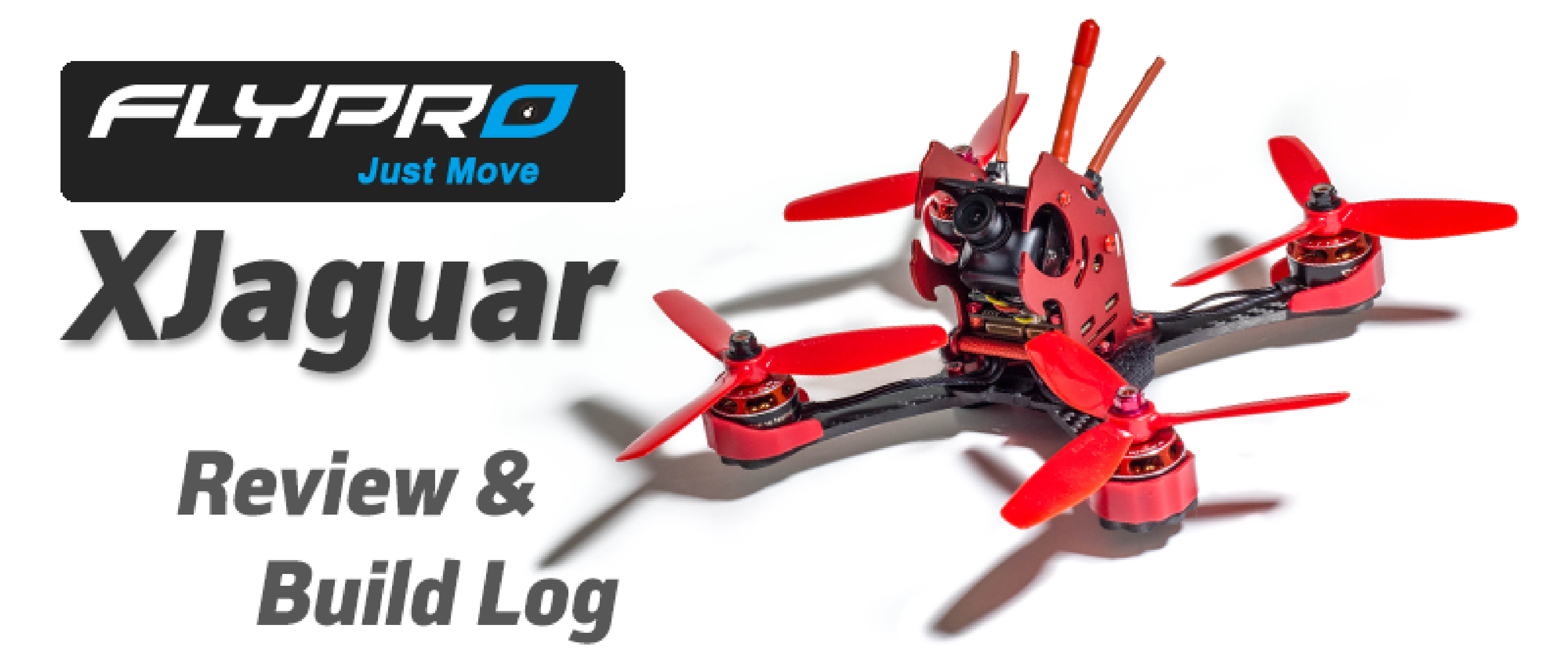
I was contacted by Flypro to check out their new “BNF” quad and so I couldn’t really say no - it has a very interesting design (some will love it, some will hate it) - but what stood out to me was the components used in the kit. The kit comes unassembled and has everything you require except for a receiver, and aims to be a competitive racer right out of the box. There would have been a Lipo included but they faced shipping issues with their courier so it was not included.
You can checkout the Flypro XJaguar on their website here, I’m not sure currently where you can buy it, but I’m sure there will be retailers soon. I had first heard of Flypro at Drone Worlds, they were one of the sponsors of the event, and it looks like in their product lineup they are very much focused on Aerial Photography rigs, but are venturing into the mini quad market - this is great! Regardless of how the product review goes, it’s great to see companies starting to invest in this sport and realising the potential of it :)
What’s in the box?
So what do we get for our cash, this is meant to be essentially a BNF kit.

We get a box! I actually quite like this box, packaging often leaves a lot to be desired but the packaging here is simple but effective.
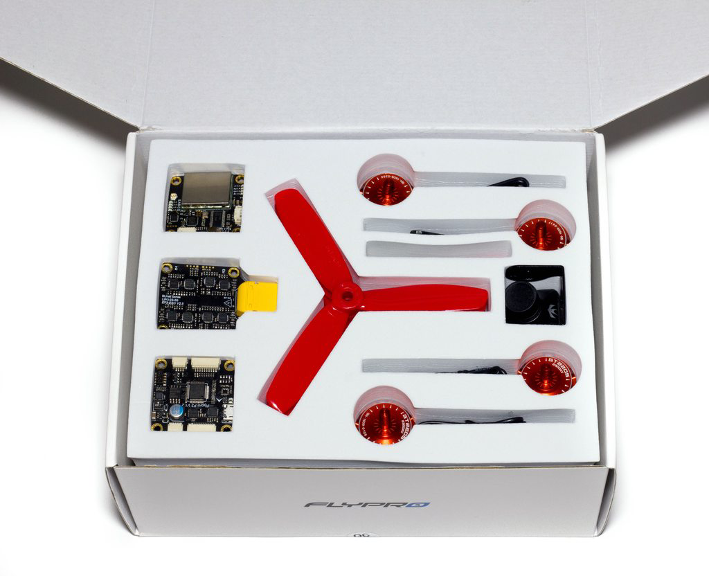
Upon opening the box we are presented with some of the key components of the build - you’ll immediately notice we have 3 stackable 30.5x30.5mm boards. These make up the ‘guts’ of our quad - featuring a VTX and OSD on one board, a set of 30A BLHeli (not BLHeli_S) speed controllers on another, and at the bottom we have the F3-based flight controller. They all connect up together without any wiring and it’s all a very smart bit of kit, but we’ll get onto that further down. In the middle we can see we’ve got some 5045x3 DAL Propellers, that will be used to power the RCInPower 2205 2300kv motors. And finally we have a RunCam Swift - a great FPV camera - it’s great to see a company FINALLY make use of some decent CCD cameras, far too often do they skimp in this area and bring out the rubbish CMOS cameras. Good job so far!
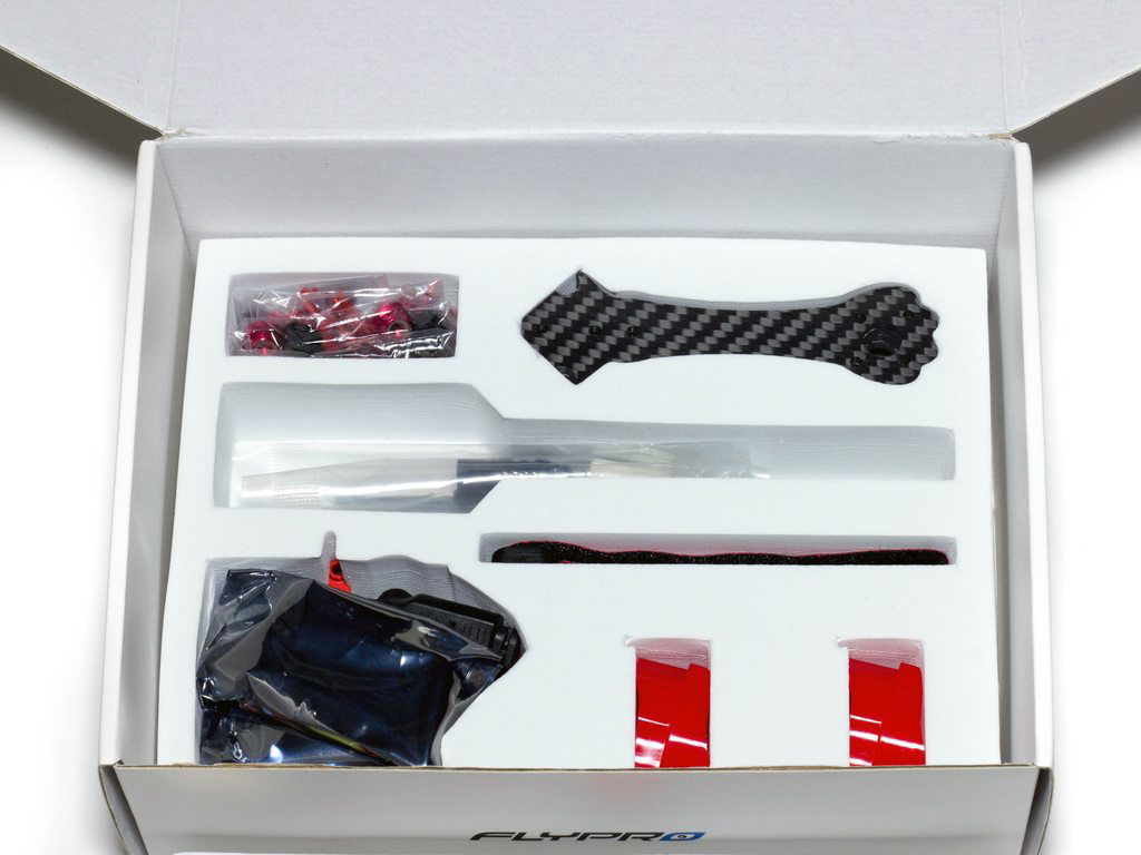
Lifting out that set of components we can see we have the rest of the kit, some red anodised hardware, bits of the frame, motor protectors and all of the other accessories that go with it.
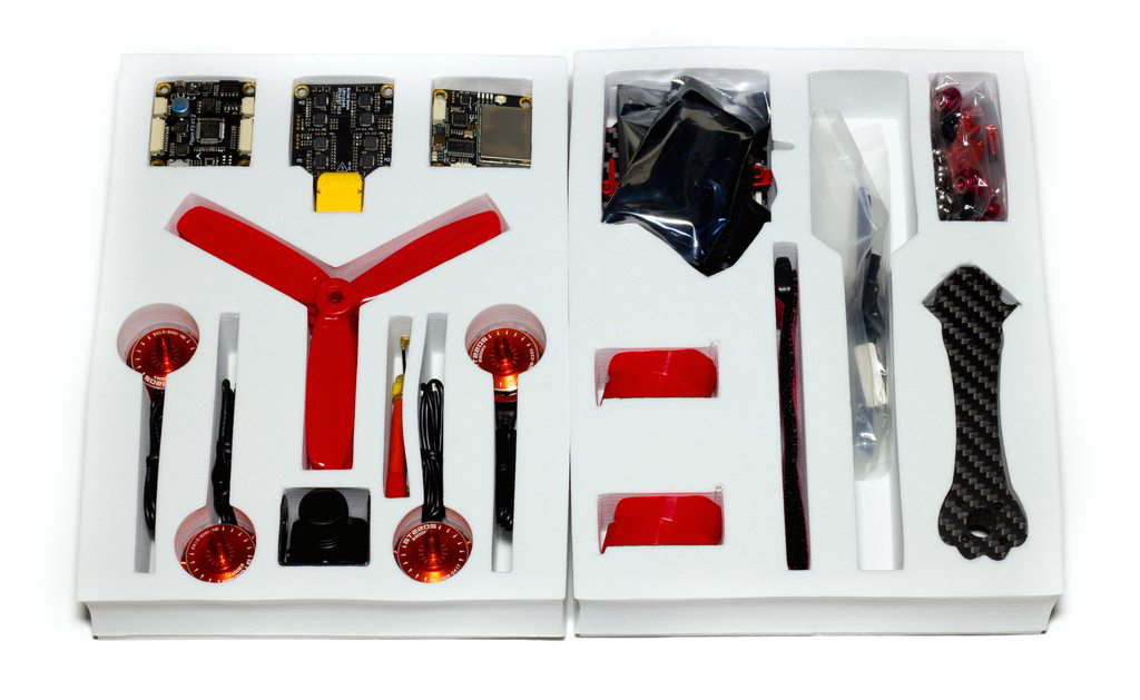
Here’s the kit as a whole.
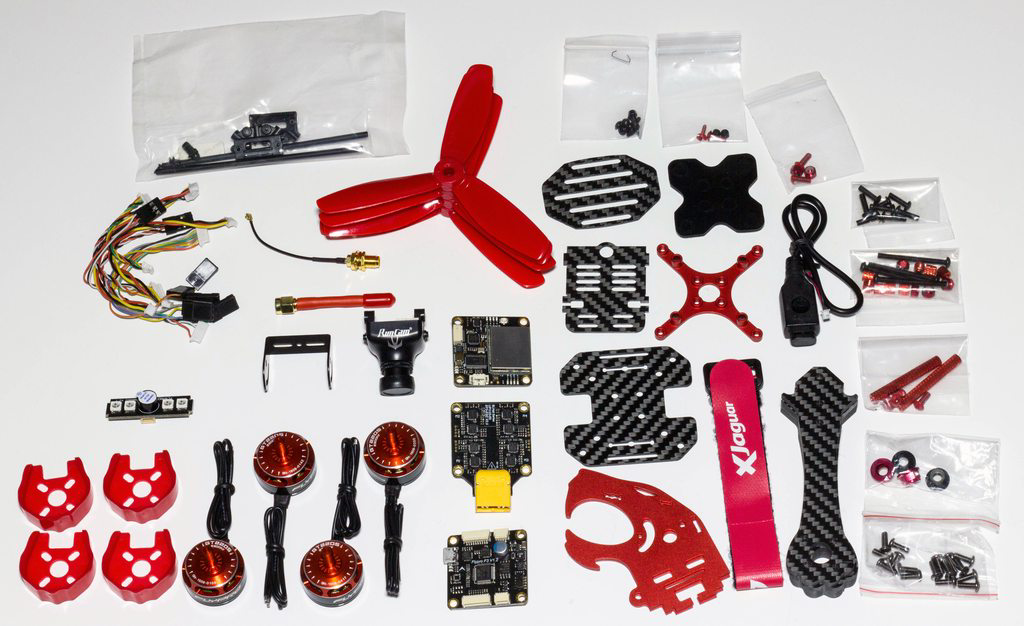
With everything taken out of the box we can see there’s a lot of good quality components with the kit. I’m excited to get building it for sure!
The Build
So the first thing I notice is that there’s no paperwork at all inside the box, nothing, nada. Don’t get me wrong I’ve built a ton of frames in the past, but for something like this you really need to build it exactly as it was intended so after a bit of searching online I came across a manual here which outlines where all the parts go together, but not exactly a manual. I can see people who are new to the hobby picking up a kit like this because it has everything they need except for transmitter/receiver and something to receive the video. I know for a fact those people will struggle because it took me a few minutes to work out all the different size bolts there are, and there’s a few “gotchas” along the way which I’ll highlight as we go.
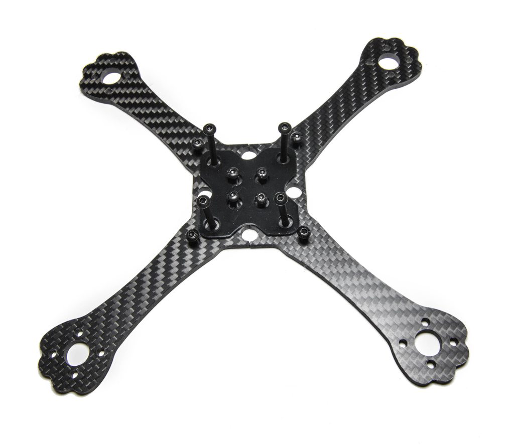
First things first we need to stick the battery protector to the arms - this gives us the bottom rigidity of the frame (which is a little worrying if I’m honest), and helps keep the arms together before we add in the top plate. I’ve also added the screws here ready to flip it.
NOTE: The arm orientation DOES matter. I found this out way down into the build when I came to add the motors in, but I would recommend screwing the motors to the arms FIRST. Not only are the arms directional, but the motors are also directional too (they have CCW and CW locknuts), so screw these up first and set them up in an X shape for the correct direction.
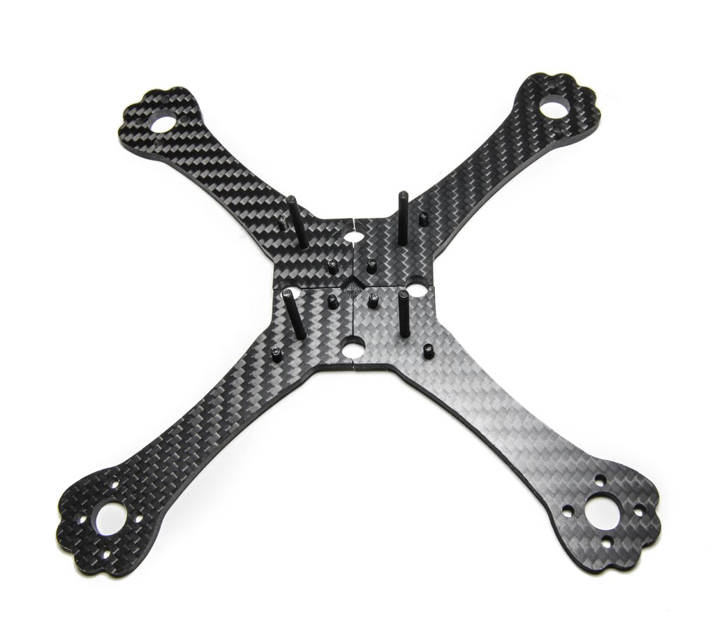
Once we’ve done that we can flip the arms (with all the screws still in), and get ready for the next step.
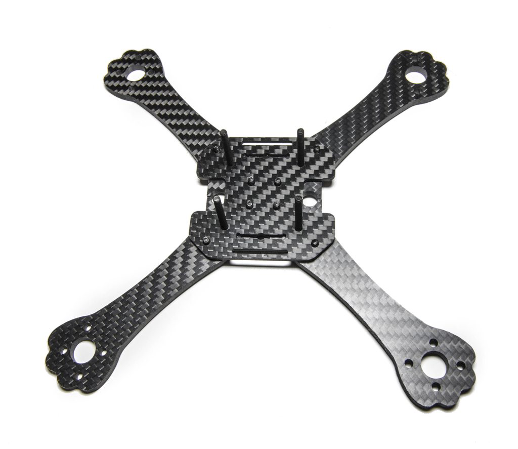
Now we can add on the upper frame brace plate. This houses a slot for the XT60 in the larger cutouts, and and also has slots for the battery strap. If you have the motors on already you can work out which is the front and back easily, so orientation of this plate is essential for the later build steps.
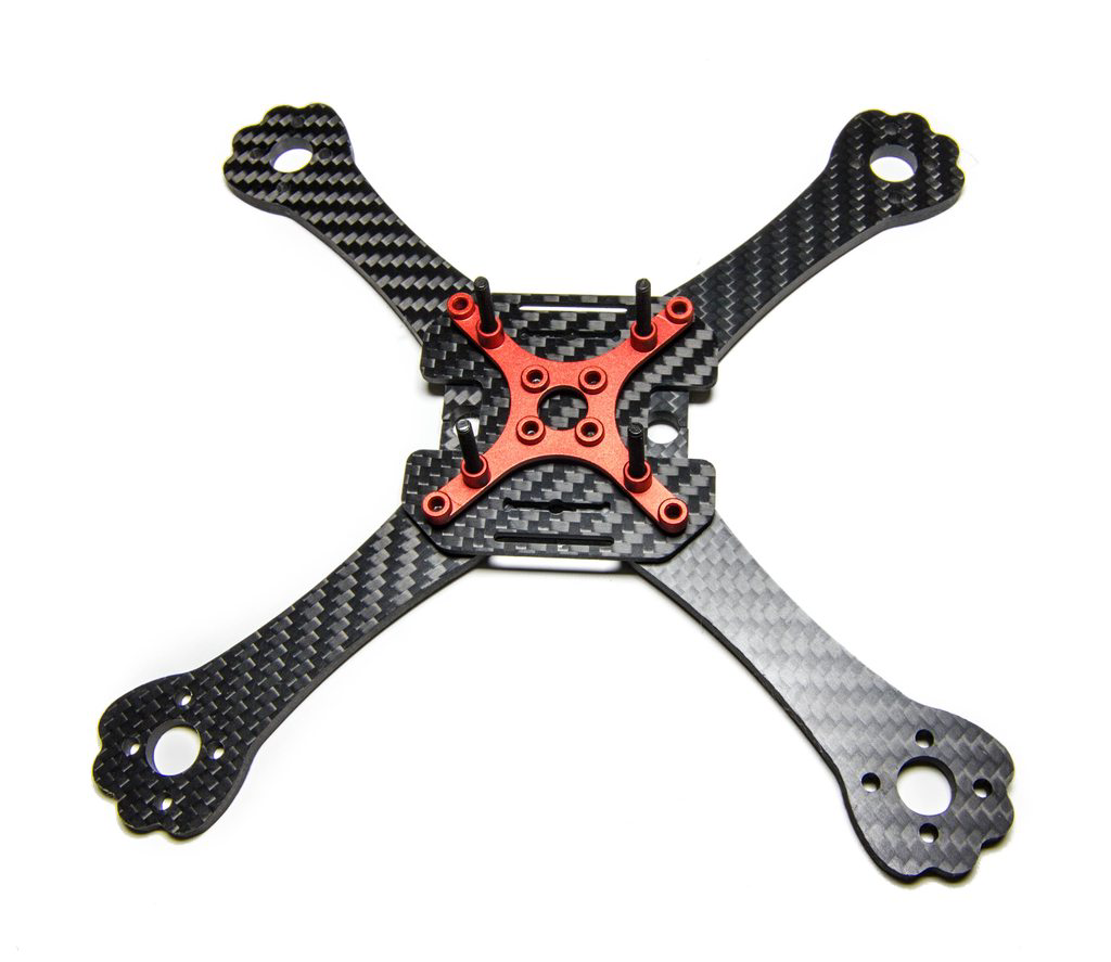
Next we can add the red frame brace, this has threaded holes that bring the whole bottom half of the frame together. I’m a little worried about stripping these in a hard crash but we’ll see how it holds up in test flying!
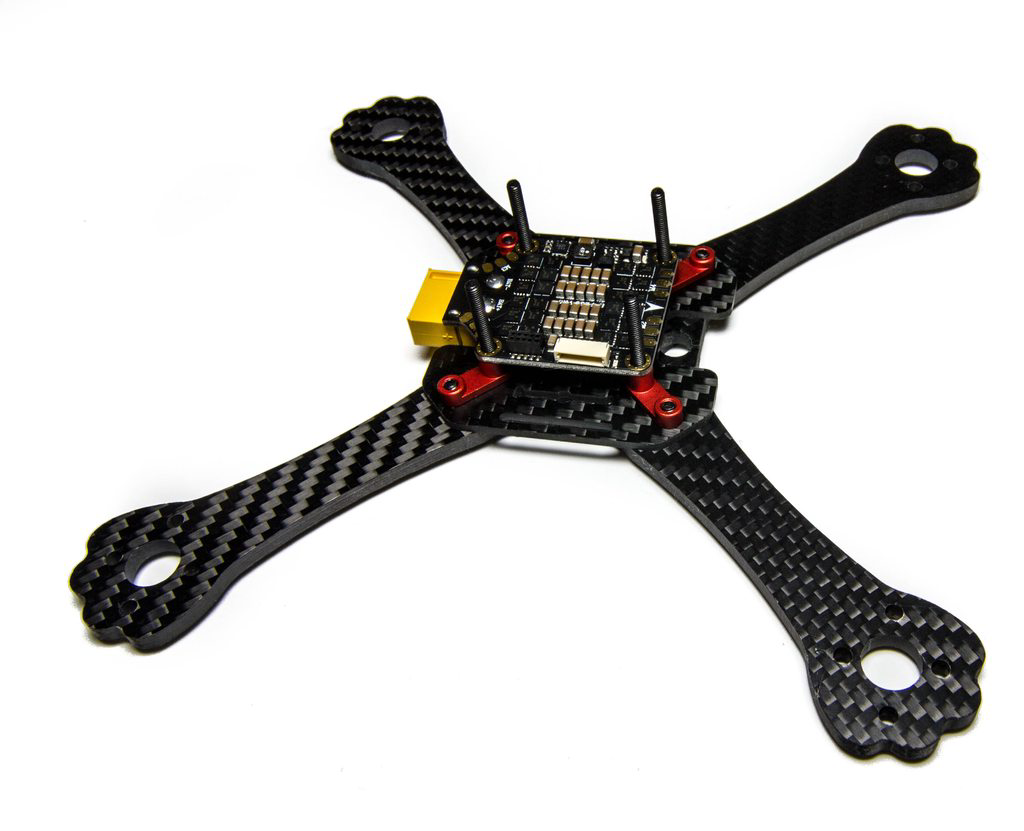
With that done we can now add the ESC’s - the first steps of the electronic side of things. This fits really nicely onto the build with the XT60 being secured extremely well. My only criticism here would be that they are BLHeli ESC’s and not BLHeli_S. If you look closely on the bottom left of the board you can see some pin header terminals - this is how all 3 of the boards connect, making for a very neat wireless setup. It reminds me of the TBS PowerCube setup that utilizes similar techniques.
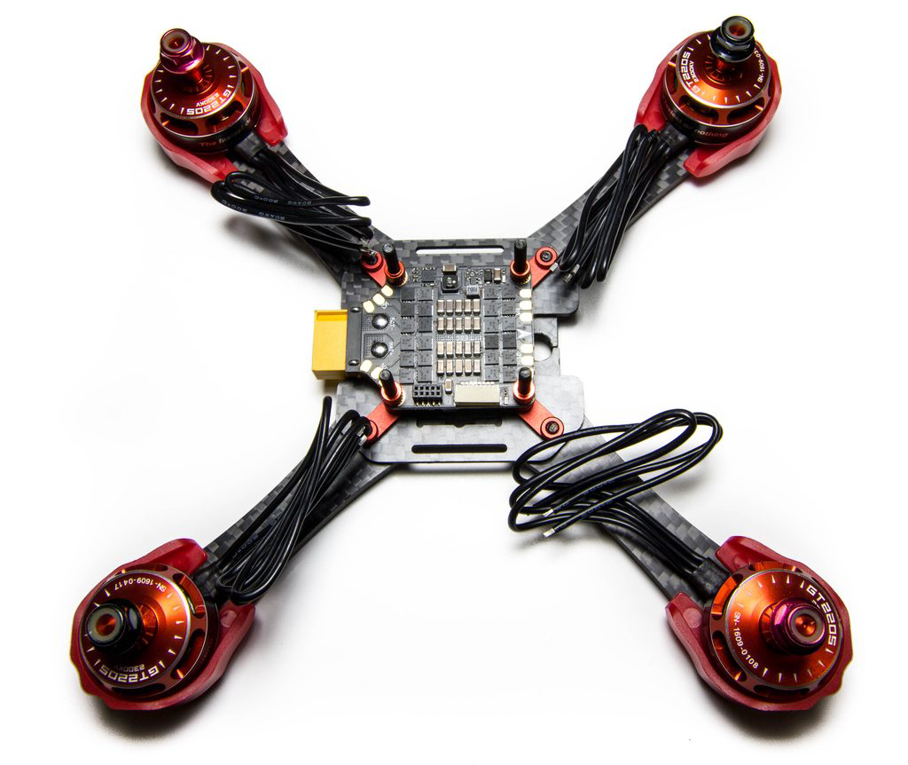
As above you’ll know I wish I had added the motors onto the arms first, but after a bit of pain working out why the screws did not fit I finally had the motors in. The motors are completely directional on the arms as the arms only feature screw holes for the 16mm and 19mm pattern, they do not have slots. Therefore you have to put the motor on the correct way otherwise you cannot screw it in.
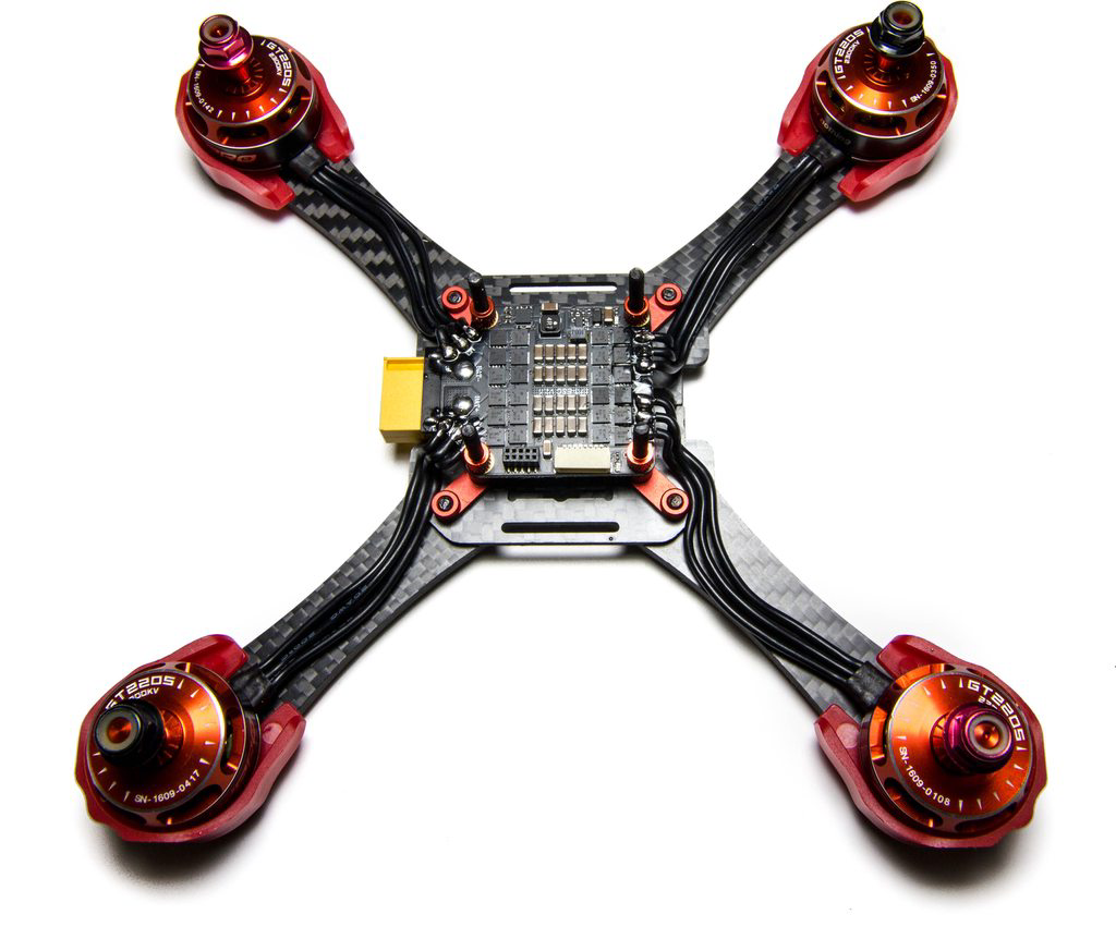
We can then shorten the motor wires as much as possible while maintaining a tidy build. I’ve also added on the red aluminium spacers just above the ESC’s ready for the flight controller to be installed.
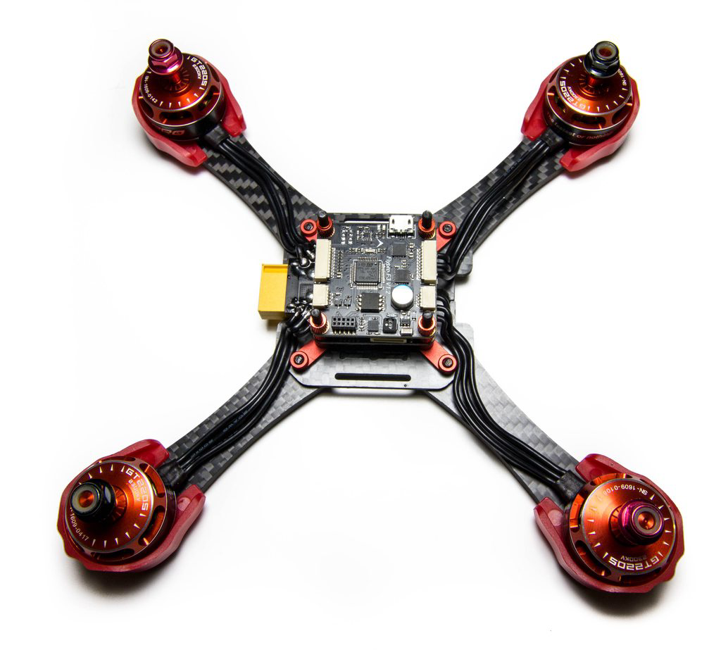
The flight controller is now added, this is an F3 based FC that has all the features you’d expect. It looks like it has it’s own onboard 5v regulator so the pin terminals likely just supply battery power throughout the stack (including the OSD and VTX). We can then add on the final set of aluminium spacers to the stack ready for the VTX and OSD.
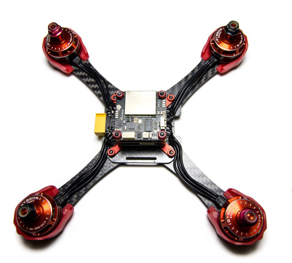
The VTX and OSD is now in place and looks to be a very tidy bit of kit, sporting it’s own uFL connector similar to the ImmersionRC Tramp and TBS Unify video transmitters, I’m glad they have decided to go this way and not use a hard-soldered pigtail. Again, no wires here makes for a tidy install. I presume one of the connectors is used for the camera.
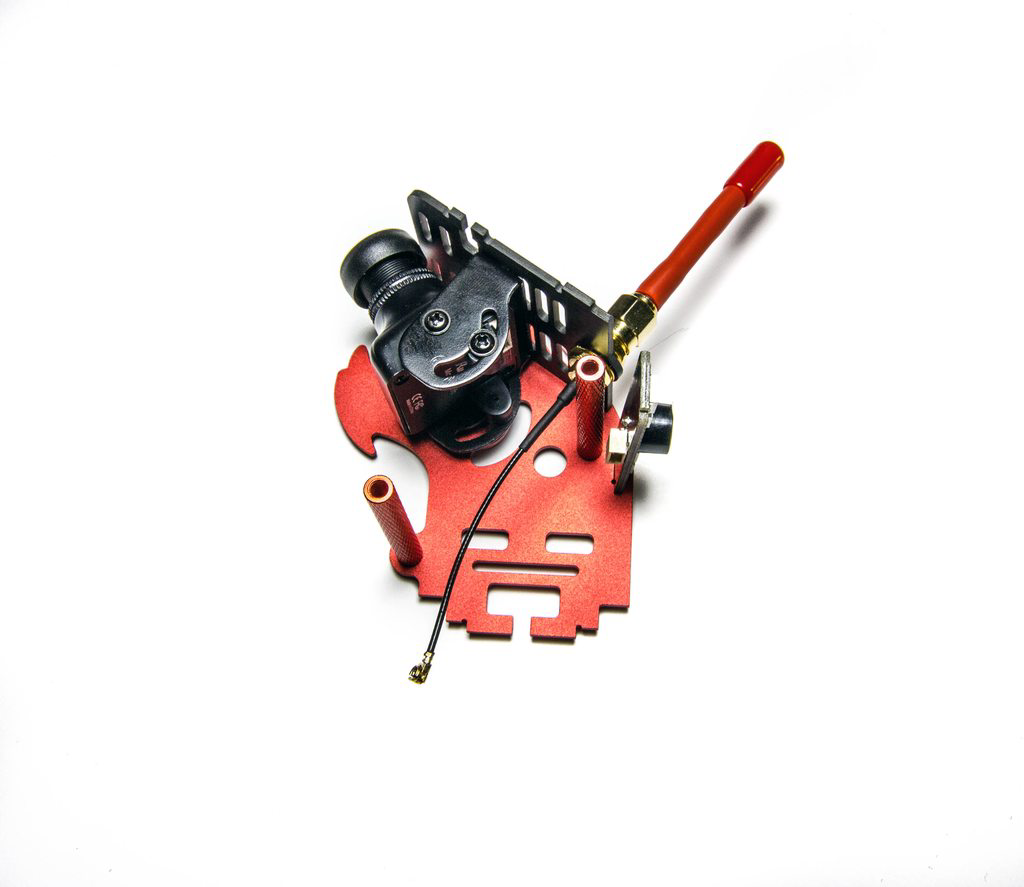
With the main quadcopter finished we can move onto building up the aluminium pod that sits on top of all of this. The fact this section is completely aluminium does kind of scare me when it comes to crashing, as it has a habit of bending - which could mash all of the components below it, and it would lose its shape quickly. Nevertheless, we’ll see in testing. We’ve got the RunCam swift added to the top plate which also houses the SMA connector along with the provided linear antenna. We have some structural metal standoffs that keep horizontal rigidity and at the back you can see we have a little PDB that features programmable LED’s and a buzzer all in one nice little package.
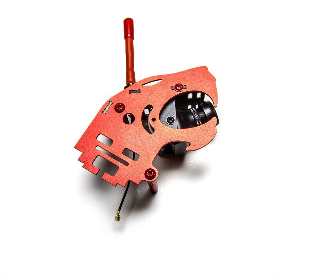
From the other side you can see we get all this from just a few screws, the key thing is working out which screws go where of course!
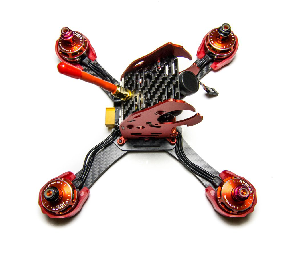
All that is then left is to slide the pod over the electronics stack and slot it into the frame. Once we’ve done that there are two final screws and locknuts which secure it in place. I’m not sure of the locknut design on this - I’ve seen it on a few frames and for me it seems like it would be easy to ruin that small bit of material that secures it all in place, especially on aluminium where it would bend.
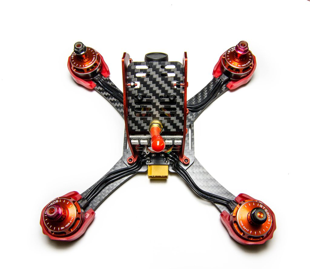
And a top side view of the quadcopter, a very tidy build I must admit, this is now with all of the wires hooked up.
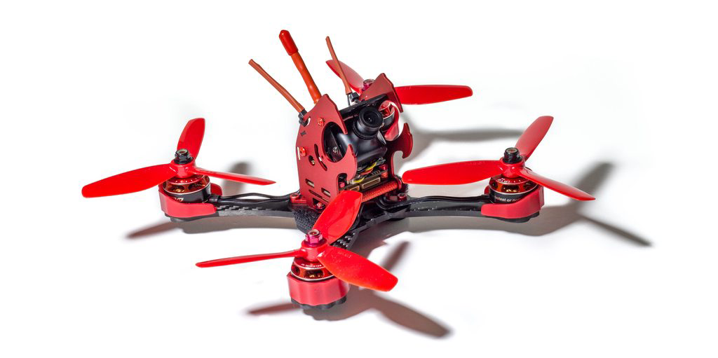
Now we have the receiver in place and the antennas are attached to the top of the frame. It does come with a mechanism for the antennas which consists of some straws and a moulded plastic holder, but if you’ve flown at all you’ll know these straws soon get damaged beyond repair and a cabletie with heatshrink does a far better job, and they never break.
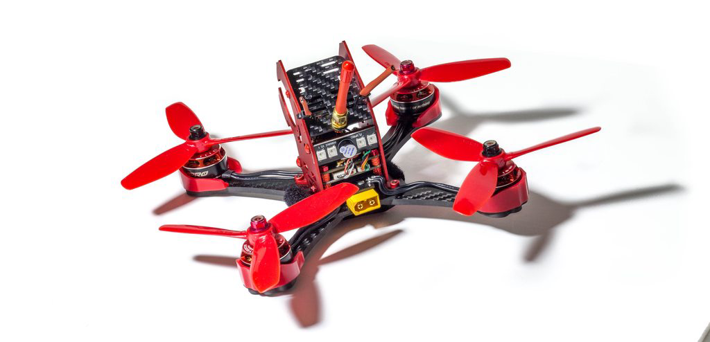
Here’s the backside view of the quadcopter, we can see there’s very few wires here and it looks an extremely tidy build.
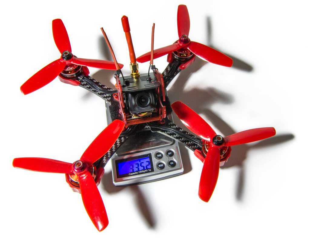
And there we have it, the whole quad including battery straps and propellers weighing in at 335.2 grams. That is a very respectable weight, in fact it is far lighter than any other quad of this kind (I’m thinking Vortex or Vendetta). This does indeed have the weight potential to become a racing frame, we just need to see how it holds up to the crashes :)
Pre-Flight Setup
Due to the target market (racers), I think there’s some stuff we’d have to do here before actually flying it. The XJaguar comes pre-setup with Cleanflight which is the first thing for me to change, as I think Betaflight feels better in flight and is smoother. Flashing the target (SPRF3 layout) was simple enough, as was setting up the configuration to allow the OSD, and LED’s. Everything else was left stock (including PIDs) to see how it handles ‘out of the box’. I know this is not true OOTB, but feel this is an important step.
I’ve also gone and changed the lens on the RunCam Swift to a 1.8mm lens, removing the current stock 2.8mm lens. I did fly it once on this lens but it is just far too narrow and not what I’m used to at all.
So with that in mind, let’s get some flying in!
As we can see it can get some speed up no issue due to the great selection of components we have in the kit. It also seems to take crashing way better than I thought.
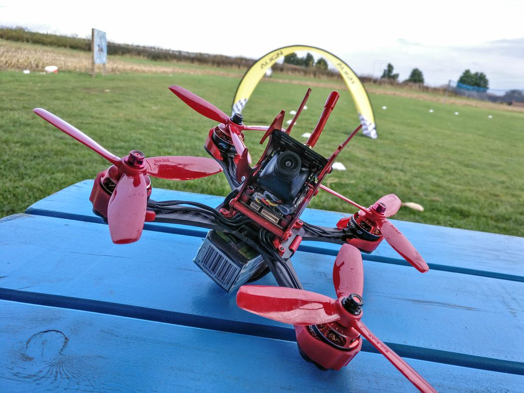
As we can see in the above picture part of the metal (on the left) is bent out of shape. I had just bent it back, but I can tell that a few crashes would end up snapping it for sure as it weakens with each crash.
Conclusion
This is quite a nice ‘racing’ kit that has all of the parts you would need to be competitive at a racing competition. It would also fit a GoPro on top should you wish to freestyle it or carry a HD cam when racing.
Pros
- Everything you need in one kit with good motors, FPV equipment and a nice tidy stack
- RunCam Swift which is a great FPV camera - so many “BNF” or “RTF” quads lack a good camera, it’s good to see a CCD in a build like this, key for racing.
- It’s one of the lightest “BNF” quads I’ve seeing, weighing in the same sort of weight as my current racing quads.
- Linear antenna for a cheap part of the cost, allowing you to buy your own race antennas when you are not practicing.
Cons
- Little to no build instructions with awkward and fiddly stages
- Metal top-section will get ruined after a few heavy crashes, potentially destroying inner components
- Frame (imo) needs a bottom brace, aluminium brace liable to stripping on heavy crashes where arms are the main crashing section
- BLHeli ESC’s leave a little to be desired, these really need to be BLHeli_S now I think.
- VTX Channel changing can be cumbersome, and features differences to others on the market.
So there we have it, an actually quite impressive build that offers what I think a potential solution to the market we currently face. It does have it’s ownsides, but if you can get past those, then it would make a great quad for racing with.