Posts
Shrike Top Plate Redesign
Posted on April 16, 2016 • 9 min read • 1,750 words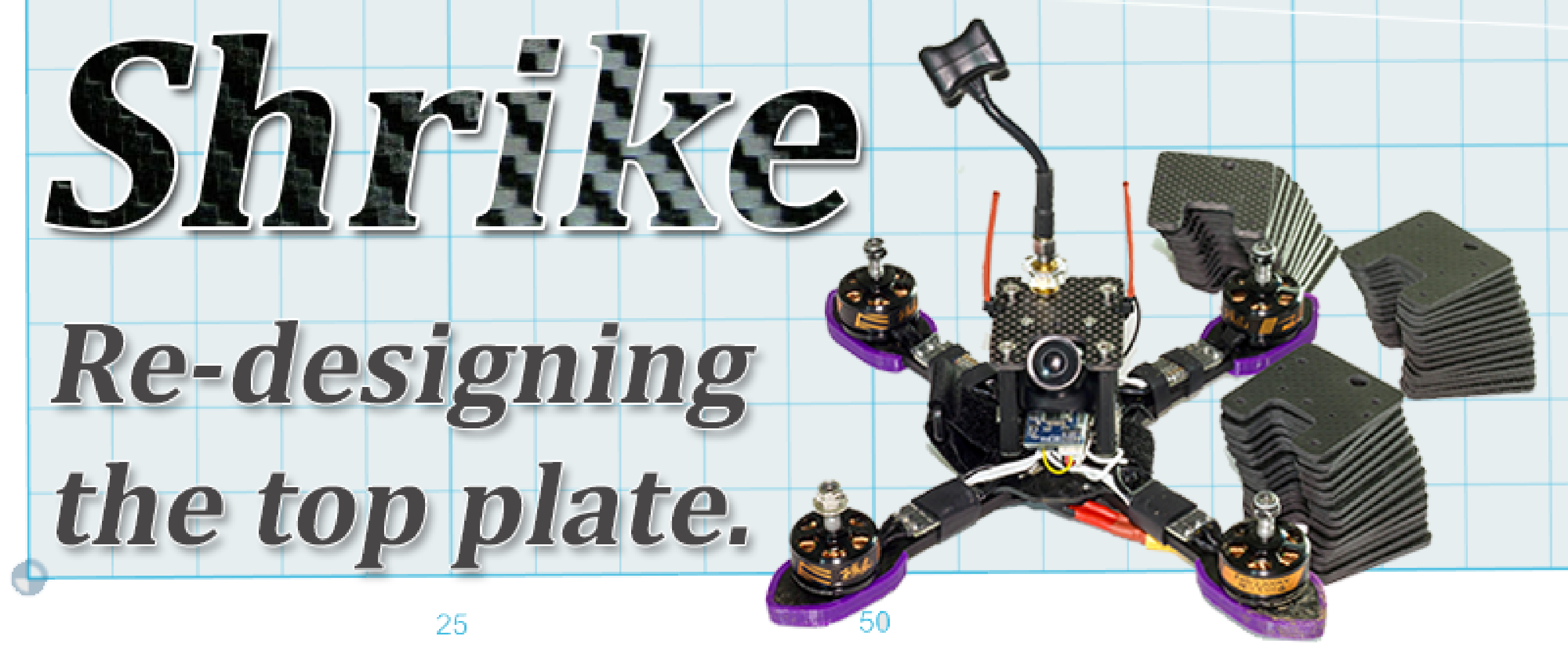
Why? Carry a GoPro without fear of breaking anything. When? The past 6 months…! How? 3D Modelling, 3D Printing & Carbon CNCing.
The Problem
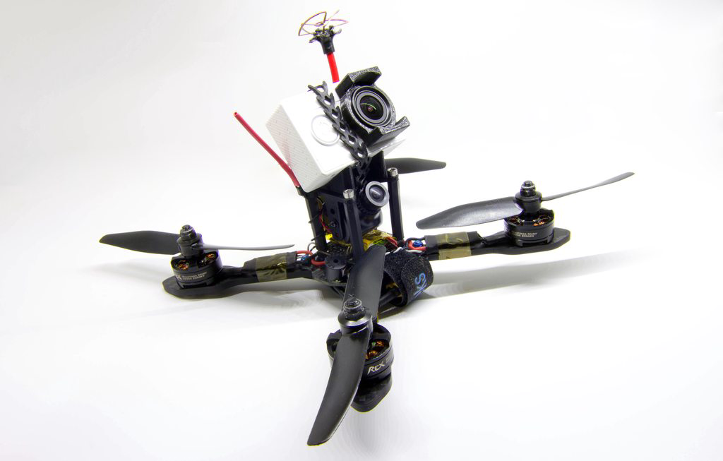
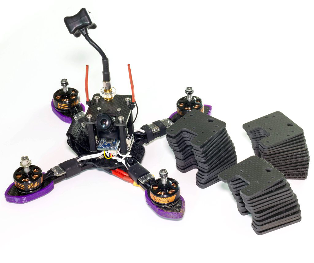
So as we know the Shrike is a super lightweight X-based racing frame. It excels in having an extremely good power to weight ratio depending how you spec it up, and even with that in mind it still has 4mm thick arms meaning even the harshest of crashes result in no damage (I am still yet to break anything, but let’s hope this doesn’t jynx it… :)).
When I first built the Shrike a few months back in it’s stock form it had one purpose - pure racing. While this is good, I love getting great GoPro footage, so for me this isn’t the most ideal. So with that being said, why is the stock top plate annoying, and why did I change it? Well simply put - the antenna location is not good. If you run a Mobius, you can probably still mount it fine and have a good amount of angle on it. However, for a GoPro you will struggle because it’s much wider than it is tall, meaning no matter how you mount it you will be fouling the Antenna.
Prototype Version 1
For the first iteration of my design I wanted to keep the top plate design similar to the original so did just that, keep the curves and profile of the existing design, but simply adding in an angled wedge for the GoPro.

With the basic GoPro design added, the SMA was slotted in at the back so that I could keep it out the way of the big GoPro side profile. I quickly realised in testing the design was not great - the super thin arms going towards the screw locations are a bad idea for 3d printed designs as there is just not that strength required to survive crashes.
Designing version 2.
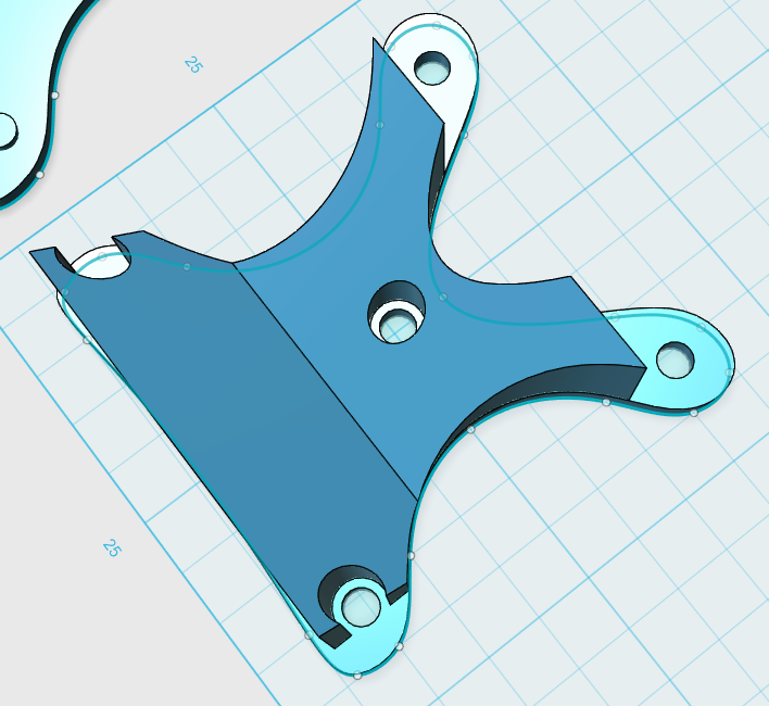
With the above items in mind I set about designing something from the ground up. I had now got used to the tools of the modelling software and felt comfortable in designing something a bit more advanced and practical for the Shrike.
Having had my 3d printers for just under 2 years now I have a good experience of where it’s strength lies - when you need a flat plate to be strong you need to make it as thick as possible, so with that in mind I started with a flat plate and added in what was required. The design was kept simple, adding curves where required that wouldn’t reduce strength too much.
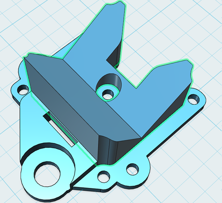
I quickly realised after testing this version that actually, using M2 hardware for mounting the HS1177 is far better than a single M3 screw in the middle - it keeps the camera frame MUCH more rigid and will stop most of the vibrations when flying.
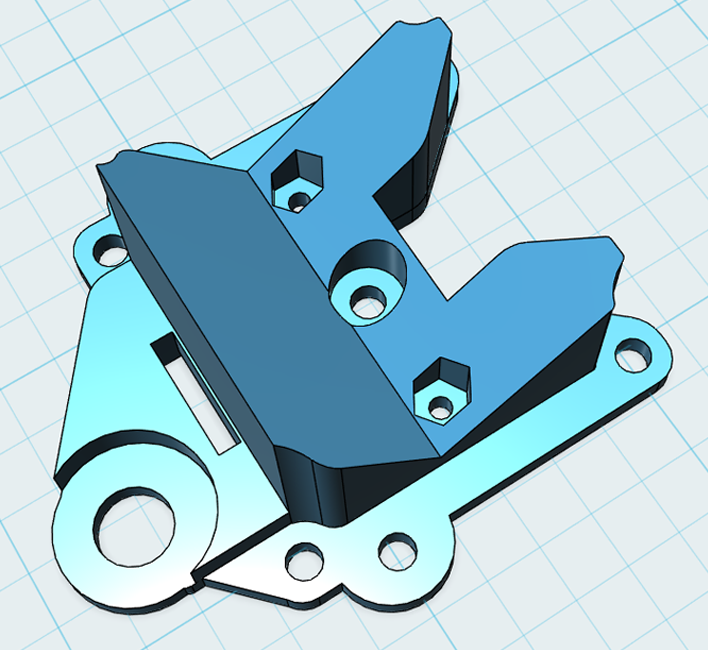
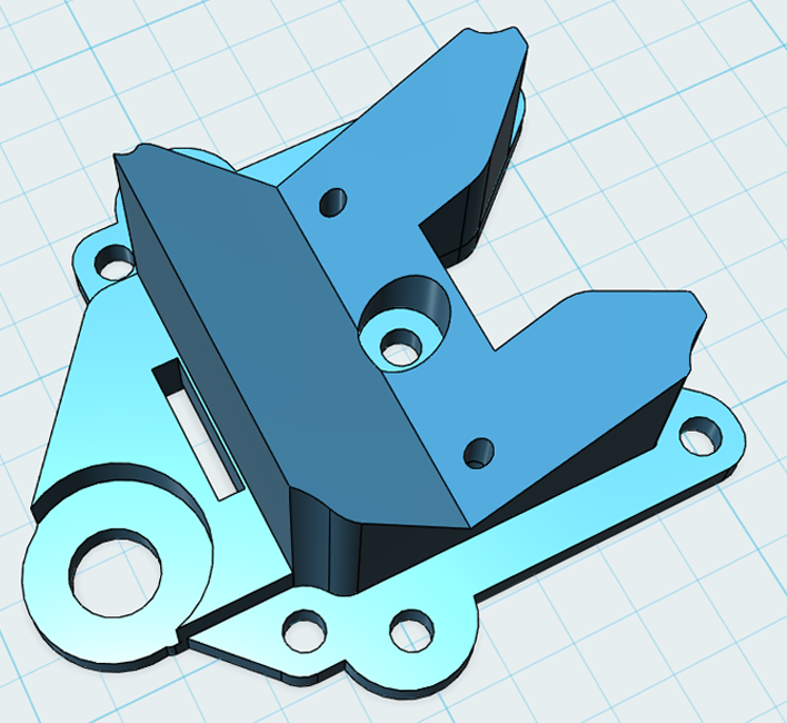
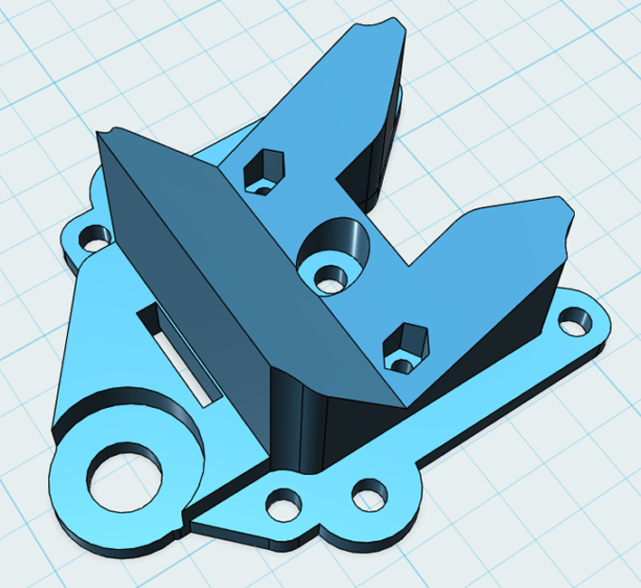
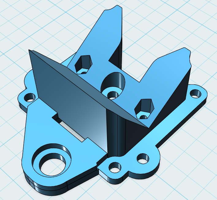
After testing that prototype the M2 hardware worked good, but it made sense to integrate some more functionality into the mount so I added some hex-shaped holes to allow nuts to slide in - this makes it far easier to change and use the brackets only requiring a screw driver to change the bracket, or shift it onto another frame.
During testing the mount was working well, I was no longer breaking it where the M3 screws are for the standoffs but instead having a few SMA mount issues. Realising there is just not enough material in place for the SMA I created a new revision to reinforce where the SMA sits. There is still a cutout for the SMA on the antenna to sit within the mount, but the extra material behind it, it just adds a lot more strength.
With that done, test flights worked well. The only issue I had then was the GoPro seemed to sit pretty hard against the antenna, so that in a hard crash (I’m still using Rapstraps at this point), the GoPro would push back and still break the SMA mount. The rear design was changed slightly and positioned the GoPro a little further forwards to help combat that issue.
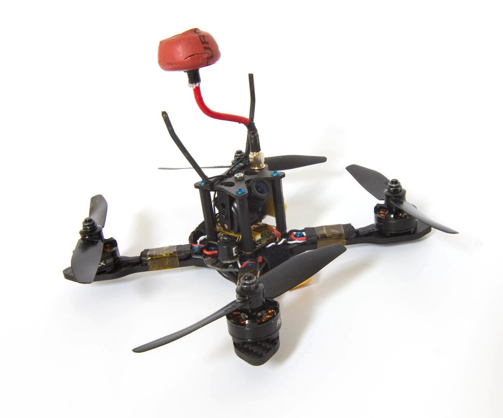
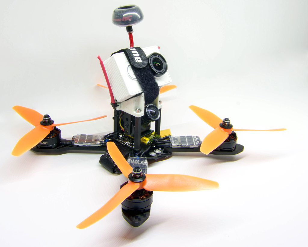
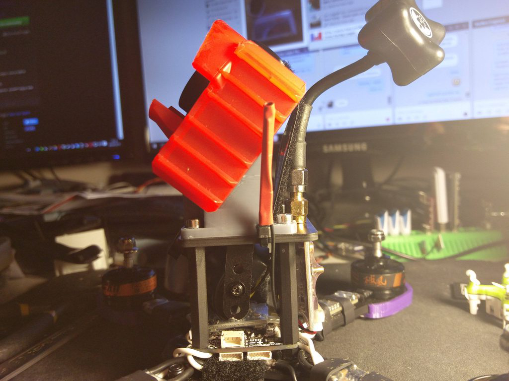
A quick picture of the V3 on the Shrike, looking pretty fresh and OEM.
The final version?
After a few more weeks of flying I quickly realised that while the Rapstrap idea was good in theory, in practice during a crash the GoPro ejecting felt like a good idea - having to keep finding the GoPro after a crash was a nightmare. It also meant that with no GoPro on the quad, the SMA was left vulnerable again which defeated the point of my mount if it was breaking every time.
With that in mind, I started from the ground up again. The design didn’t change too much from the original, but I kept in mind that I wanted to use a full size battery strap to secure the GoPro permanently even in a crash. This would reduce all of the load from the SMA connector - the only current weak point of the mount.
With that in mind I printed some more of these and got to work testing them thoroughly because who doesn’t crash all the time? :D. I spent around 3 months with this design and it works awesome - I only broke one M3 screw part on one mount, otherwise I did all the crashing in the world on grass and they survived very well.
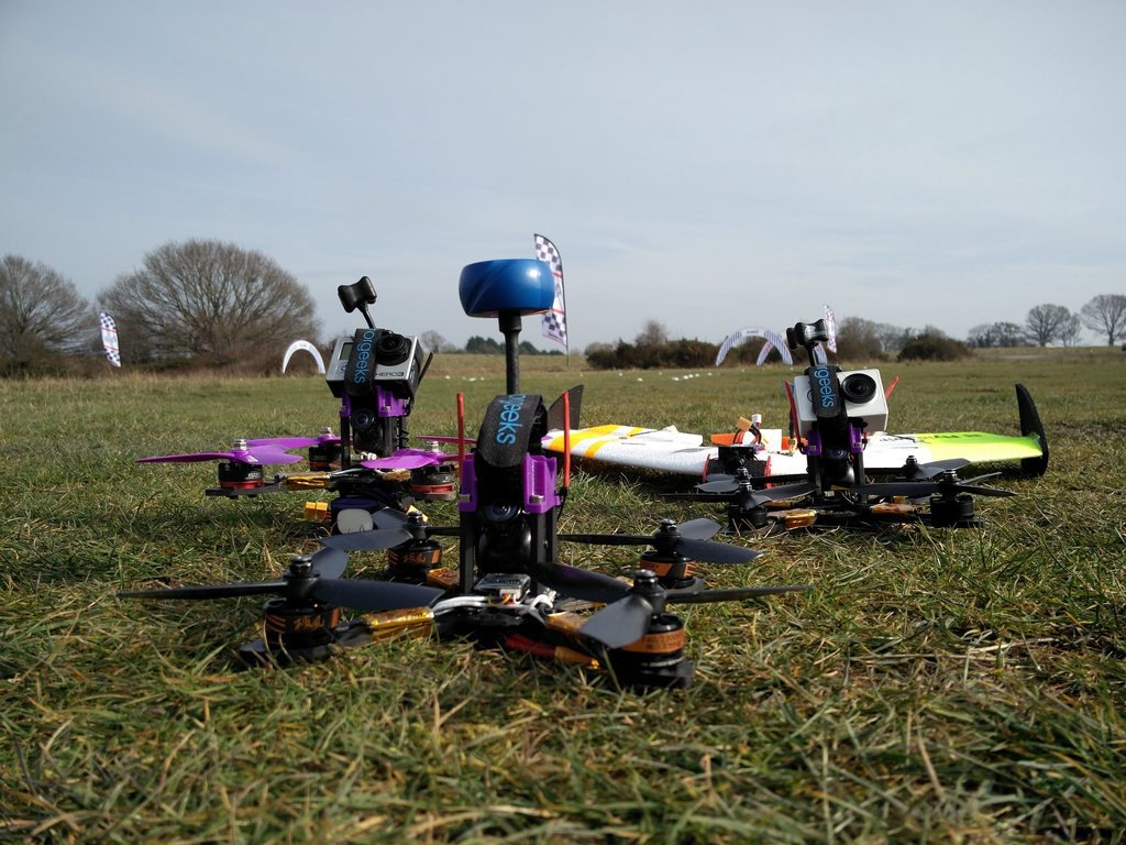
During this time I acquired a couple more Shrikes and kitted them out with the same mount. They were flying awesome and more importantly they were robust when carrying a GoPro :)
The final final version!?
What’s this, ANOTHER version you say? Sadly so.
I was flying in a concrete warehouse a few weeks back and sadly found what concrete does to 3d printed plastic in even the smallest of crashes. Part of it was my fault, I had not bent the antennas back so when I landed perfectly upside down onto a solid concrete floor it just pushed the antenna straight down, snapping the SMA part of the mount cleanly off.
For me, this is a failure of design again, and not something I wish to just risk when flying - we have quite a few indoor events over the UK and with more varying events coming up, I need a quad that will work in all conditions without issue. I knew that waiting for a Shrike revision, or someone else to design a solution would be no good so I set about creating my own. I’ve learnt that if you want something, don’t wait for someone else to do it, just do it yourself. :)
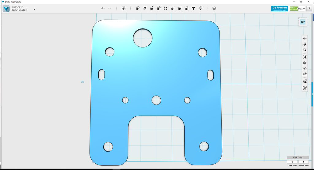
With that in mind I set about creating a basic top plate design. Shaving weight by adding loads of cutouts was not something I even considered - the weight loss is too minimal compared to the strength loss of cutting. It’s not even just the fact you are creating weak points, but every time you cut you are potentially creating slight delamination points all around that area from the vibrations, so keeping it as simple as possible was key.
With a basic design one I printed it out to check all measurements were ok before getting some Carbon CNC quotes from various recommended vendors. I found CNCMadness to be by far the most reasonable price-wise and they were super quick in cutting and shipping them, I couldn’t have asked for any more from them. I did a mini UK group buy of the plates with some friends who I had previously done a Shrike group buy for and we waited a week or so for them to arrive.
I decided to get the plates cut in 2mm, 2.5mm and 3mm - the cost was so small it made sense to both try various sizes and also get a reasonable amount of spares cut just in case there is a flaw in the carbon or the in my design.
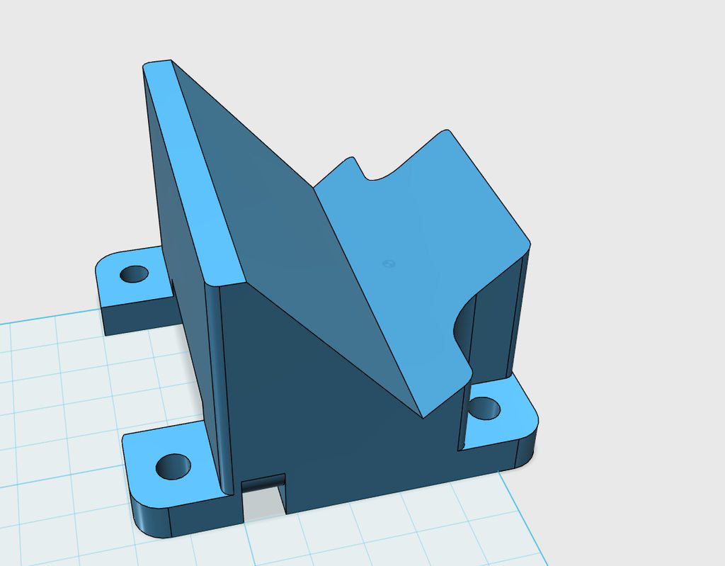
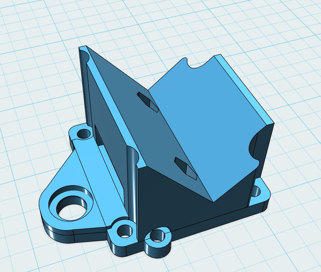
With the carbon now here I could now start designing a new GoPro mount. I did roughly 4 revisions and printed it each time, before finally landing on the current revision you see above. The design should work very well.
I can run the Shrike with or without a GoPro without fear of smashing up the SMA mount and killing VTX’s or antennas. It also means that if I do actually break the GoPro mount, it’s super simple to replate as it’s just 4 screws, no messing around removing the camera or the vtx and antenna.
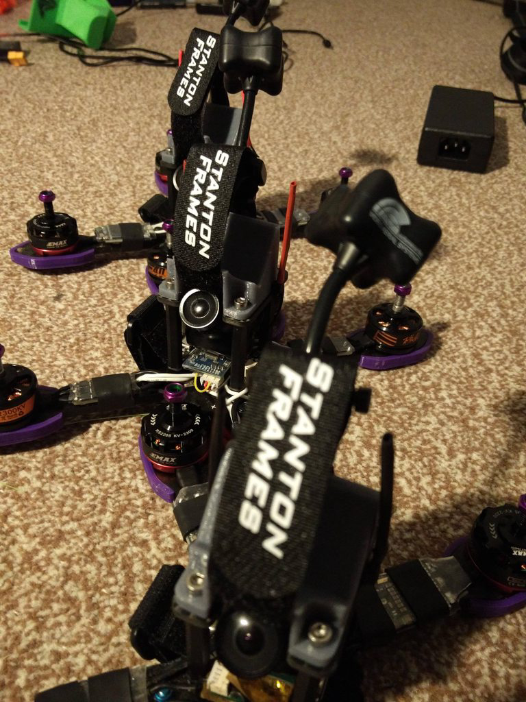
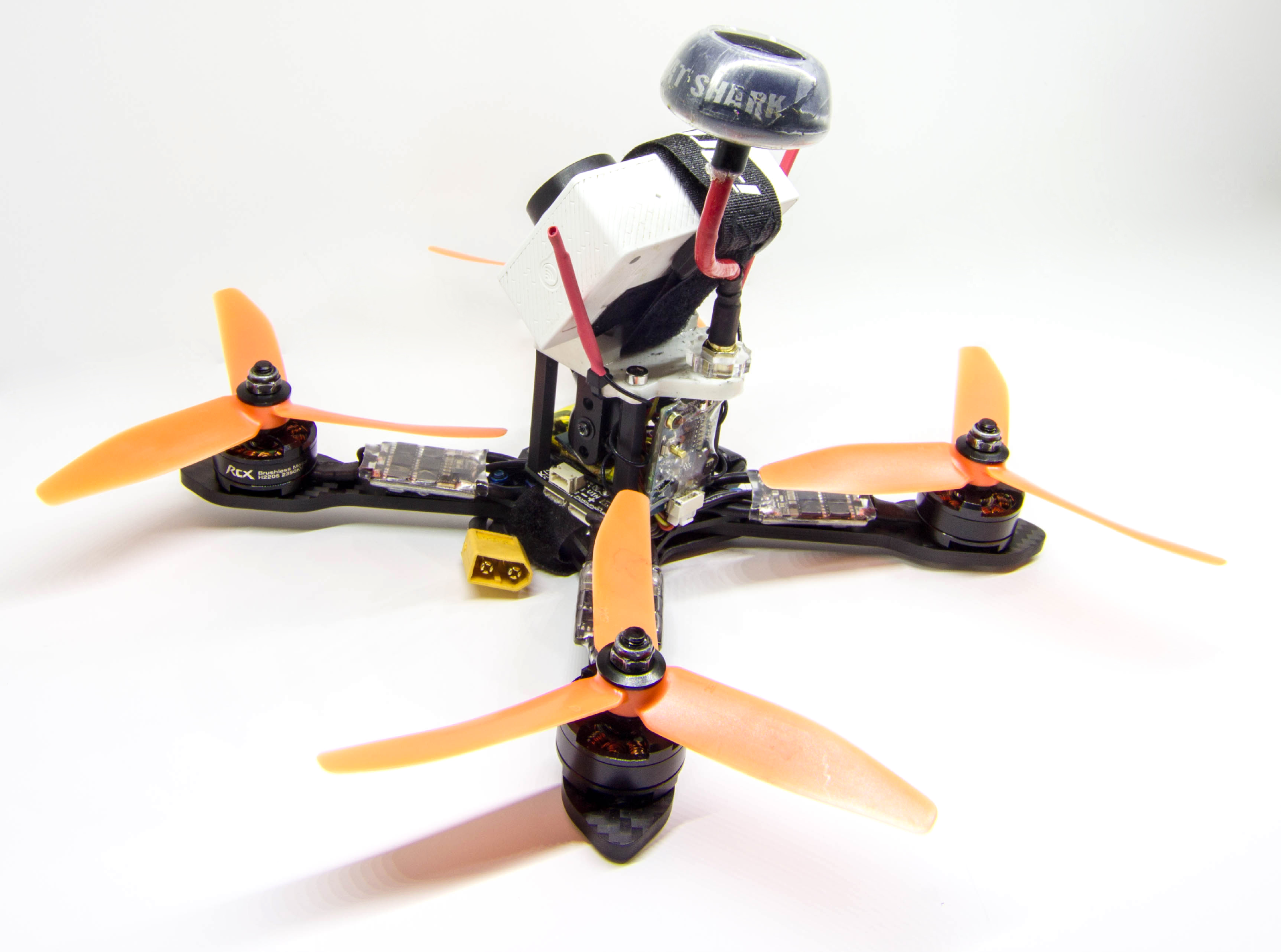
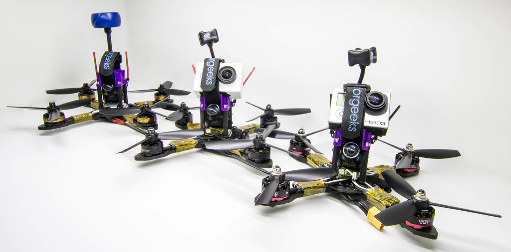
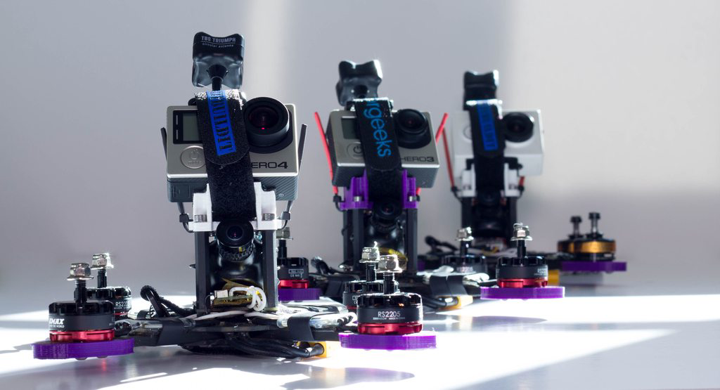
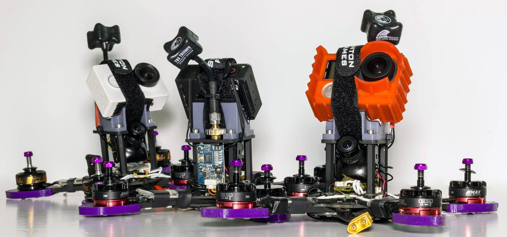
And here we have the end product printed and mounted on all my Shrikes. I am currently running the 2.5mm thick carbon plate, which works really well as the SMA and antenna mount fits perfectly without any issues. It’s also 25% thicker than the stock plate, and with the improved design, I don’t think I’ll be breaking it any time soon! :)
It’s been a very fun and new experience, I haven’t done much 3d Modelling since University so it’s good to get back into it. The thing I love about this hobby is having a 3d printer opens up the world of possibilities for so much custom design work. If you have an idea you can just create it, long gone are the days of being disappointed when you see a flaw and cannot fix it.

And like my other designs and creations, the full files can be found on Thingiverse here.
You can also download my previous revision (v4) here - it still works well, but the newer Carbon version is much stronger. :)