Posts
Designing & Printing a Lumenier / TrueRC AXII uFL Antenna Mount
Posted on November 8, 2017 • 6 min read • 1,144 words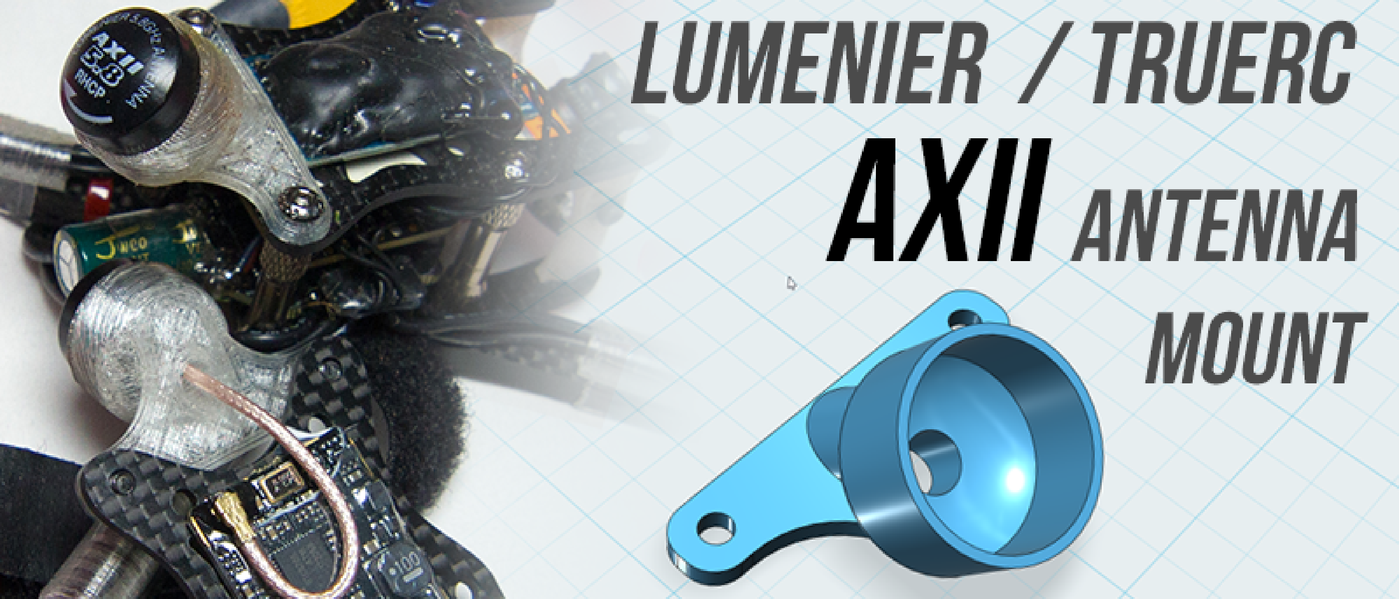
You can find the Antenna mount with source files on Thingiverse available here aka https://www.thingiverse.com/thing:2572243
If you’re like me, you’ve gone to races or even the field to have a fly and you break antennas left, right and center from bad crashes or just bad antenna placement. On a lot of frames it’s pretty much impossible to actually protect an antenna well enough but still get a good fpv feed, but this is about to change if you haven’t seen already!
Innovative designs on antennas have made them smaller, stronger and better than ever for receiving/transmitting signals, but with that comes with one issue - all that crash force has to go somewhere, and this has inevitably led to breaking antennas at the SMA, breaking the plates they are attached to, the pigtail or even the VTX. Now that the Unify and other fantastic VTX’s attach via uFL instead of an SMA connector, we’ve seen antennas follow suit, with much smaller and ligher footprints. With that, comes the difficulty of mounting the things into your frame, whether it’s via cableties, glue, or some 3d printed mount, there was nothing out there that suited my own personal needs.
I wanted something light, something robust, and something that would give me good signal. And thus, I designed the mount from the ground up!
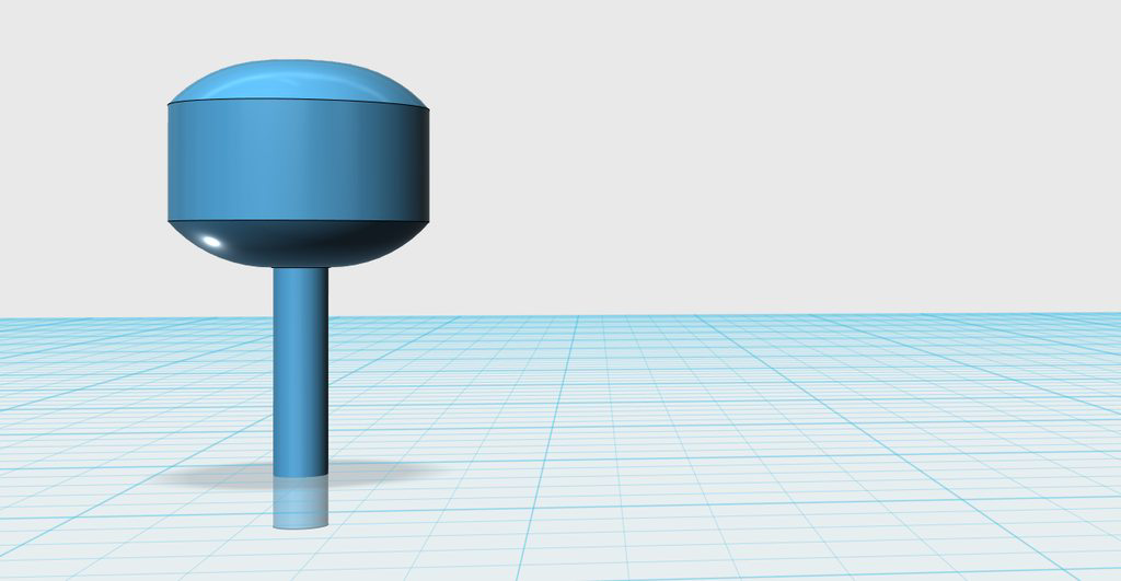
The first step to any accurate design is ensuring the part looks and fits into your design - for this reason I ‘cloned’ the exact dimensions, or as close to as I could of the Lumenier AXII. It differs slightly to the TrueRC antenna in the fact that it has a moulded case rather than 3d printed, and is actually a little smaller.
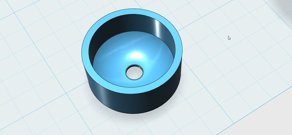
The next step involved actually creating something for the antenna to sit in. I knew that my 3d printer extrudes at a 0.45mm width, so sensibly I configured the walls of the part to end up being 0.9mm thick - aka 2 perimeters for printing. This allows me to get a perfect print without any gaps that a 1mm wide print usually would - or it would even try and infill the remaining 0.1mm, which ends up overfilling and making the wall thicker than it needs to be.
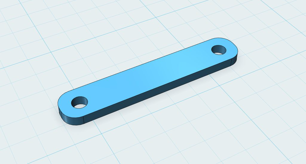
The next step was to create the mount - what would actually attach to the frame. I’m intending to primarily run this on my Falcon Multirotors Featherlight 5", but in reality most frames run with the screws spaced at 30.5mm - the same width for flight controllers. This meant the design can be used by many people for many different frames, without anyone having to modify the main project file.
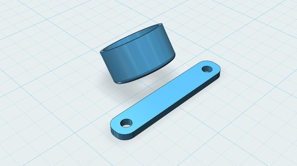
The next step was positioning the antenna relative to the screw holes. It had to be far enough away that carbon would not affect video signal, but close enough that it would not flex majorly, or stand out in a crash. Something else I also considered was the angle required to keep it flat when flying in “fast forward flight” (FFF).
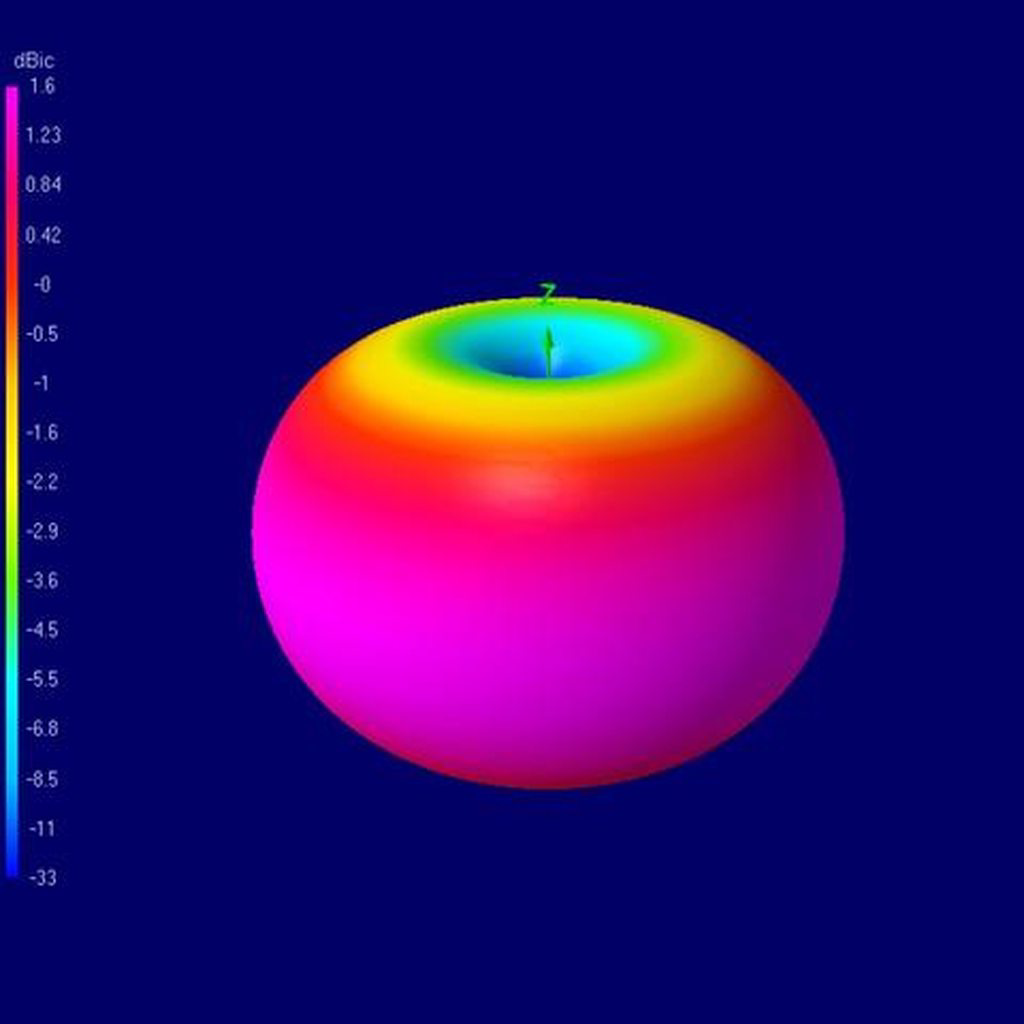
Antennas, if you know any science behind them, have pretty big deadzones in them directly out of the top and bottom of the antenna, and the signals for the most part are shaped like doughnuts. optimum signal is received on the side of it. For this reason I opted to run the antenna with a 40 degree slant, due to being a stretch X frame I have found I need less tilt, and my camera has been around 40-45 degrees for the most part when flying a track, so this made perfect sense.
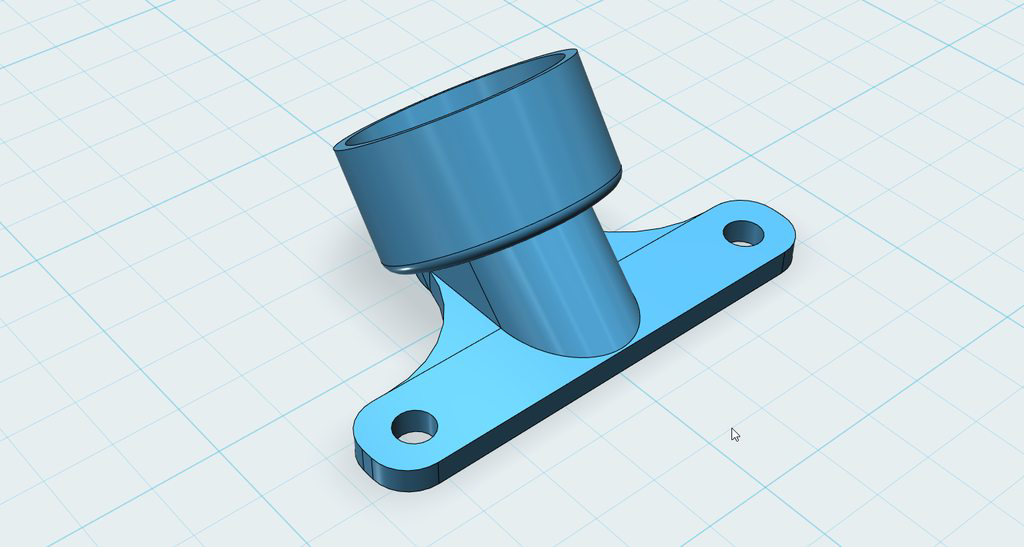
With all that done, the only thing left to do is to join them together! I initially started with just the middle cylinder and cut it where I needed to so that the underside was flat so it would easily sit on the carbon, but also would have a good printing surface. After a little thought I then added the side plates that join more material between the cylinder and the screw mounts so that it would not flex as much. Flex is good, but we don’t want too much otherwise we’ll end up wearing out the coax cable or the ufl connector.
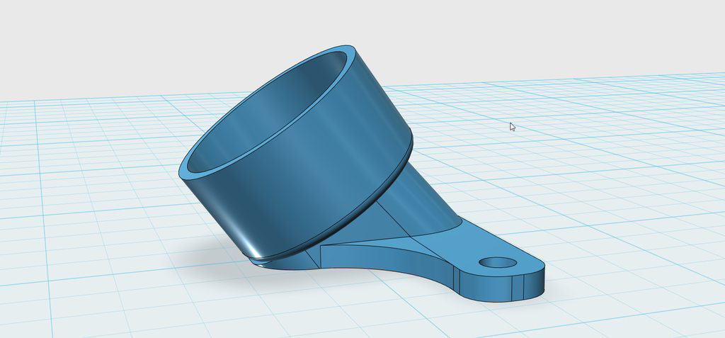
I opted to run a 2mm thick screw plate as this is a good amount of tpu which keeps the antenna solid during normal flight, but allows it to flex backwards in the event of a crash and force is applied to the antenna.
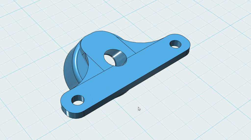
From the bottom of the part we can see the uFL hole is rather big - it’s oversized compared to the coax to allow the uFL connector to slide through without any issues, after all we’re supported the antenna via the case rather than the coax or the uFL itself.
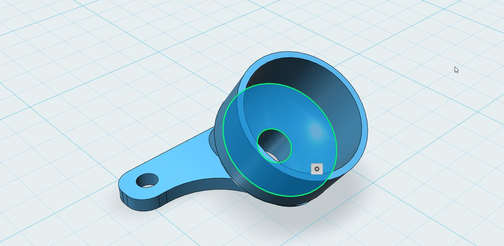
Initial test prints of the part were perfect, the antenna fitted perfectly with just enough gap on the walls to remove it with a little force. The only modifications I performed was to reduce down the bottom antenna seat as far as I could, but leaving enough material that it will still print well. I ended up saving around 0.7 grams by weight saving, leaving the total weight of the antenna mount WITH the entire antenna just 3.6 grams heavier than a whip (linear) uFL antenna!
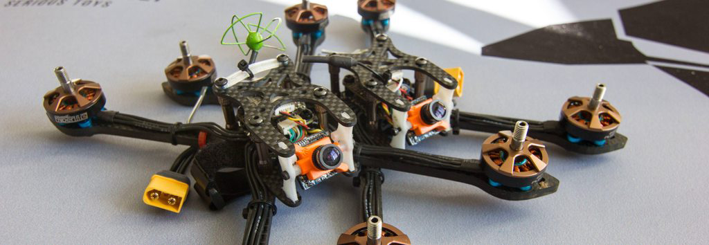
As you can see, before the antenna mount, I was looking at all sorts of ways to try and mount a good antenna - these are sub 200g race builds that have to be kept light in order to get the most out of them.
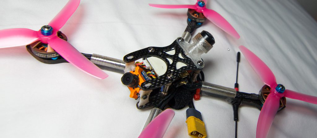
With the antenna mounted we can see how much better and practical it all looks. I’ve actually got my best video signal ever using this antenna and mod with this combination, flying there multiple times on multiple setups, so that has truly surprised me. To only add 3.6 grams, and get a proper circular polarised antenna that is basically indestructible is weight WELL spent.
I hope you enjoyed my breakdown of the antenna, found the mount and want to print it if you didn’t know about it already, or just had an interesting read! I design useful things that appeal to me, so if you like what you see please check out my other designs on Thingiverse. If you are wanting something relatively simple designed but cannot do it yourself then please feel free to contact me and if I have time and an interest in it I’ll see what I can do :).
You can find the Antenna mount with source files on Thingiverse available here aka https://www.thingiverse.com/thing:2572243